Monitoring : is for understanding what is happening in your system.
Alerting : is CloudWatch component, is counterpart to monitoring, and it allows the platform to let us know when something is wrong.
Recovering : is for identifying the cause of the issue and rectifying it.
Automating
Alert:
Simple Notification System:
CloudTrail: with enabling CloudTrail on your AWS account, you ensure that you have the data necessary to look at the history of your AWS account and determine what happened and when.
Amazon Athena: which lets you filter through large amounts of data with ease.
SSL certificate: Cryptographic certificate for encrypting traffic between two computers.
Source of truth: When data is stored in multiple places or ways, the “source of truth” is the one that is used when there is a discrepancy between the multiple sources.
Chaos Engineering: Intentionally causing issues in order to validate that a system can respond appropriately to problems.
Monitoring concept
Without monitoring, you are blind to what is happening in your systems. Without having knowledgable folks alerted when things go wrong, you’re deaf to system failures. Creating systems that reach out to you and ask you for help when they need it, or better yet, let you know that they might need help soon, is critical to meeting your business goals and sleeping easier at night.
Once you have master monitoring and alerting, you can begin to think about how your systems can fix themselves. At least for routine problems, automation can be a fantastic tool for keeping your platform running seamlessly [Source].
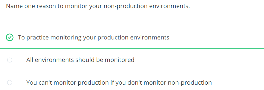
Monitoring and responding are core to every vital system. When you architect a platform, you should always think about how you will know if something is wrong with that platform early on in the design process. There are many different kinds of monitoring that can be applied to many different facets of the system, and knowing which types to apply where it can be the difference between success and failure.
CloudWatch
CloudWatch is the primary AWS service for monitoring
it has different pieces that work together
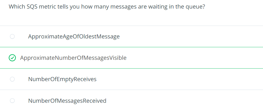
CloudWatch metrices are the main repository of monitoring metrics e.g. what does the CPU utilization look like on your RDS database, or how man messages are currently in SQS (Simple Queue Service)
we can create custom metrics
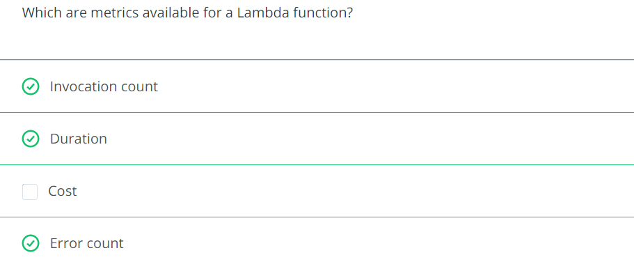
CloudWatch Logs is a service for storing and viewing text-based logs e.g. Lambda, API Gateway,…
CloudWatch Synthetics are health checks for creating HTTP endpoints
Proper alerting will help you keep tabs on your systems and will help you meet your SLAs
Alerting in ways that bring attention to important issues will keep everyone informed and prevent your customers from being the ones to inform you of problems
CloudWatch Alarms integrates with CloudWatch Metrics
Any metric in CloudWatch can be used as the basis for an alarm
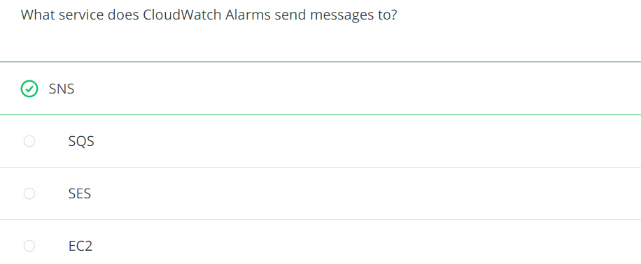
These alarms are sent to SNS topics, and from there, you have a whole variety of options for distributing information such as email, text message, Lambda invocation or third party integration.
Alerting when problems occur is critical, but alerting when problems are about to occur is far better.
Understanding the design and architecture of your platform is key to being able to set thresholds correctly
You want to set your thresholds so that your systems are quiet when the load is within their capacity, but to start speaking up when they head toward exceeding their capacity. You will need to determine how much advanced warning you will need to fix issues.
Always try to configure the alert in a way that you have a weekend to solve the problem if it’s utilization
Example: create a Lambda function and set up an alert on a Lambda functions invocation in CloudWatch Alarms to email you anytime that the Lamdba is run.
Solution has been recorded in video
Recovering From Failure by using CloudTrail
The key to recovering from failure is identifying the root cause as well as how and who/what triggered the incident.
We can log
management events (first copy of management events is free of charge but extra copies arre each 2$ for 100,000 write management events [Source])
data events (pay $0.10 per 100,000 data events)
You will be able to refer to this CloudTrail log for a complete history of the actions taken in your AWS account. You can also query these logs with Amazon Athena, which lets you filter through large amounts of data with ease.
Automating recovery
Automating service recovery and creating “self-healing” systems can take you to the next level of system architecture. Some solutions are quite simple. Using autoscaling within AWS, you can handle single instance/server failures without missing a beat. These solutions will automatically replace a failed server or will create or delete servers based on the demand at any given point in time.
Beyond the simple tasks, many types of failure can be automatically recovered from, but this can involve significant work. Many failure events can generate notifications, either directly from the service, or via an alarm generated out of CloudWatch. These events can have a Lambda function attached to them, and from there, you can do anything you need to in order to recover the system. Do be cautious with this type of automation where you are, in essence, turning over some control of the platform – to the platform. Just like with a business application, there can be defects. However, as with any software, proper and thorough testing can help ensure a high-quality product.
Some aws services can autoscale to help with some automated recovery.
Chaos engineering
Chaos Engineering is the practice of intentionally breaking things in production. If your systems can handle these failures, why not allow or encourage these failures?
Set rational alerting levels for your system so that for foreseeable issues, you get alerted so that you can take care of issues before they become critical.
Many applications and services lend themselves to being monitored and maintained. When you run into an application that does not, it is no less important (it’s like more important) to monitor, alert and maintain these applications. You may find yourself needing to go to extremes in order to pull these systems into your monitoring framework, but if you do not, you are putting yourself at risk for letting faults go undetected. Ensuring coverage of all of the components of your platform, documenting and training staff to understand the platform and practicing what to do in the case of outages will help ensure the highest uptime for your company.
Automation: The use of software to create repeatable instructions and processes to replace or reduce human interaction with IT systems
Cloud Governance: The people, process, and technology associated with your cloud infrastructure, security, and operations. It involves a framework with a set of policies and standard practices
Infrastructure as Code: The process of managing and provisioning computer resources through human and machine-readable definition files, rather than physical hardware configuration or interactive configuration tools like the AWS console
IT Audit: The examination and evaluation of an organization’s information technology infrastructure, policies and operations
CloudFormation
CloudFormation is a AWS service for create infrastructure as code.
it’s a yaml file
How to start with CloudFormation
Services -> CloudFormation
Create stack “With new resources (standard)”
Template is ready
Upload a template file
Click “Choose file” button
Select provided YAML file
Next
CloudFormation Template sections
Format version
Decsription
Parameters
Resources
Outputs
Each AWS Account has its own AWS Identity & Access Management (IAM) Service.
If you know Azure On Microsoft Azure, we have a Subscription. The AWS Account can be equivalent to the Azure Subscription. With a difference. Each AWS Account can have its own IAM Users but in Azure, we have a central IAM Service, called Azure Active Directory (AAD). Each above-called service is a huge topic but we don’t do a deep dive right now.
The AWS IAM User can be used
Only for CLI purposes. This user can’t log in to the AWS Portal.
Only for working with the AWS Portal. This user can’t be used for CLI.
Both purposes. This user can be used to log in to the AWS Portal and CLI.
Pipeline User
The first question is why do we need a Pipeline User?
Automated deployment (CI/CD) pipeline and prevent manual or per-click deployment.
We can only grant the pipeline user for some specific permissions and audit the logs of this user.
This user can work with AWS Services only via CLI. Therefore it has an Access Key ID and a Key Secret.
If you know Azure It’s used like a Service Principal, that you have a client-id and client-secret.
Expose the API/Service Products for external customers (exposes an OpenAPI endpoint)
Includes a secure API gateway
In case of Premium tier includes an Azure Traffic Manager
Throtteling the requests to prevent resource exhaustion
Set policies
Set Cache
Key concepts
Secure and isolate access to azure resources by using Network Security Group and Application Security Group
This section is only “what should we know about NSG and ASG”. To see the configuration refer to “Configure NSG and ASG“.
By using Network Security Group (NSG) can be specified which computer can be connected to application server [Source]. – Network Security Group: is to secure network traffic for virtual machines – Virtual Network Service Endpoint: is for controlling network traffic to and from azure services e.g. storage, database – Application Security Group:
Network security group
filter network traffic to or from azure resources
contains security rules that are configured to allow or deny inbound and outbound traffic.
can be used to filter traffic between virtual machines or subnets, both within a vnet and from the internet.
The allowed IP addresses can be configured in NSG as well.
NSG rules are applied to connection between on-prem to vnet or vnet to vnet.
NSG of a subnet is applied to all NIC in this subnet
NSG of subnet and NIC are evaluated separately
NSG on subnet instead of NIC reduces administration and management effort.
Each subnet and NIC can habe only one NSG
NSG supports TCP, UDP, ICMP, and operates at layer 4 of the OSI model.
Vnet and NSG must be in the same region
Network security group security rules
NSG contains one or more rules
Rules are allow or deny
Rule properites
Name
Priority 100..4096
Source [Any, IP Addresses|Service Tag|Application Security Group]
Source Port range
Protocol [Any|TCP|UDP|ICMP]
Destination [Any, IP Addresses|Service Tag|Application Security Group]
Destination Port range
Action [Allow|Deny]
Rules are evaluated by priority using 5-tuple information (Source, SourcePort, Destination, DestinationPort, Protocol)
The rule with lower priority will takeplace e.g. 200 (Allow 3389 RDP) and 150 (Deny 3389 RDP). 150 will takeplace.
With NSG, connections are stateful. It means, return traffic is automatically allowed for the same TCP/UDP session e.g. inbound rule allows traffic on port 80 also allows the vm to response the request. A corresponding outbound rule is not needed.
Add Inbound rule pane
Service tag can allow or deny traffic to a spesific azure service either globally or per region. Therefore you don’t need to know the IP address and port os the service because azure does it for you.
Microosft create the service tags (you cannot create your own)
Some examples of the tags are:
VirtualNetwork – This tag represents all virtual network addresses anywhere in Azure, and in your on-premises network if you’re using hybrid connectivity.
AzureLoadBalancer – This tag denotes Azure’s infrastructure load balancer. The tag translates to the virtual IP address of the host (168.63.129.16) where Azure health probes originate.
Internet – This tag represents anything outside the virtual network address that is publicly reachable, including resources that have public IP addresses. One such resource is the Web Apps feature of Azure App Service.
AzureTrafficManager – This tag represents the IP address for Azure Traffic Manager.
Storage – This tag represents the IP address space for Azure Storage. You can specify whether traffic is allowed or denied. You can also specify if access is allowed only to a specific region, but you can’t select individual storage accounts.
SQL – This tag represents the address for Azure SQL Database, Azure Database for MySQL, Azure Database for PostgreSQL, and Azure SQL Data Warehouse services. You can specify whether traffic is allowed or denied, and you can limit to a specific region.
AppService – This tag represents address prefixes for Azure App Service.
service Tag
Scenario: We have a WebServer in Subnet1 and SQL Server in Subnet2. NSG must only allow 1433 for SQL.
Scenario: Suppose your company wants to restrict access to resources in your datacenter, spread across several network address ranges. With augmented rules, you can add all these ranges into a single rule, reducing the administrative overhead and complexity in your network security groups.
Network security group default rules
default rules connot be deleted or changed but can be overriden
NSG Overview
Application Security Group (ASG)
Scenario: your company has a number of front-end servers in a virtual network. The web servers must be accessible over ports 80 and 8080. Database servers must be accessible over port 1433. You assign the network interfaces for the web servers to one application security group, and the network interfaces for the database servers to another application security group. You then create two inbound rules in your network security group. One rule allows HTTP traffic to all servers in the web server application security group. The other rule allows SQL traffic to all servers in the database server application security group.
Application security group let you configure network security for resources used by specific application.
It’s for grouping Vms logically, no matter what ip address is or in which subnet assigned
Using ASG within NSG to apply a security rule to a group of resources, after that should only the resources be added to ASG.
ASG let us to group network interfaces together and the ASG can be used as Source or Destination in NSG.
Secure and isolate access to azure resources by using Service Enpoints
Scenario: The agency has created an API to make recent and historical census data available. They want to prevent any unnecessary back-end information from being exposed that could be used in malicious attacks. They would also like to prevent abuse of the APIs in the form of a large volume of requests and need a mechanism to throttle requests if they exceed an allowed amount. They are serving their APIs on the Azure API Management service and would like to implement policies to address these concerns.
add a policy to remove the X-Powered-By header from responses via adding a policy to outbound
Converts a request or response body from JSON to XML.
Convert XML to JSON
Converts a request or response body from XML to JSON.
Find and replace string in body
Finds a request or response substring and replaces it with a different substring.
Mask URLs in content
Rewrites links in the response body so that they point to the equivalent link through the gateway. by adding <redirect-content-urls /> in outbount section, all backend urls are replaced with apim endpoint url.
Set backend service
Changes the backend service for an incoming request.
Set body
Sets the message body for incoming and outgoing requests.
Set HTTP header
Assigns a value to an existing response or request header, or adds a new response or request header.
Set query string parameter
Adds, replaces the value of, or deletes a request query string parameter.
Rewrite URL
Converts a request URL from its public form to the form expected by the web service.
Transform XML using an XSLT
Applies an XSL transformation to the XML in the request or response body.
Throttling policies
Throttling
Detail
Throttle API requests
a few users over-use an API to the extent that you incur extra costs or that responsiveness to other uses is reduced. You can use throttling to limit access to API endpoints by putting limits on the number of times an API can be called within a specified period of time <rate-limit calls=”3″ renewal-period=”15″ /> and user receives 429 error when that limit was reached
#  applies to all API operations
<rate-limit calls="3" renewal-period="15" />

# target a particular API operation
<rate-limit calls="number" renewal-period="seconds">
    <api name="API name" id="API id" calls="number" renewal-period="seconds" />
        <operation name="operation name" id="operation id" calls="number" renewal-period="seconds" />
    </api>
</rate-limit>

#it applies the limit to a specified request key, often the client IP address. It gives every client equal bandwidth for calling the API
<rate-limit-by-key calls="number"
                   renewal-period="seconds"
                   increment-condition="condition"
                   counter-key="key value" />

# limit rate limit by a requests IP Address
<rate-limit-by-key calls="10"
              renewal-period="60"
              increment-condition="@(context.Response.StatusCode == 200)"
              counter-key="@(context.Request.IpAddress)"/>
# When you choose to throttle by key, you will need to decide on specific requirements for rate limiting. For example, the table below lists three common ways of specifying the counter-key:
Value	                          Detail
context.Request.IpAddress	  Rates limited by client IP address
context.Subscription.Id	          Rates limited by subscription ID
context.Request.Headers.GetValue("My-Custom-Header-Value")	Rates limited by a specified client request header value
Note: The <rate-limit-by-key> policy is not available when your API Management gateway is in the Consumption tier. You can use <rate-limit>instead.
The list of necessary commands for working with docker, docker image and container.
# pull a docker image from docker hub
docker pull mcr.microsoft.com/dotnet/core/samples:aspnetapp

# list local docker images
docker image list

# Run a Docker container. if the docker image isn't available locally, docker downloads it first
docker run mcr.microsoft.com/dotnet/core/samples:aspnetapp
# output
info: Microsoft.Hosting.Lifetime[0]
      Now listening on: http://[::]:80 # the cintainer now listening for requests to arrive on HTTP port 80 (http://localhost:80)
info: Microsoft.Hosting.Lifetime[0]
      Application started. Press Ctrl+C to shut down.
info: Microsoft.Hosting.Lifetime[0]
      Hosting environment: Production
info: Microsoft.Hosting.Lifetime[0]
      Content root path: C:\app
# Info : if we use http://localhost:80 in browser we see nothing, read below.


# By default, Docker doesn't allow inbound network requests to reach your container.
# You need to tell Docker to assign a specific port number from your computer to a specific port number in the container
# by adding the -p option to docker run.
# This instruction enables network requests to the container on the specified port.
docker run -p 8080:80 -d mcr.microsoft.com/dotnet/core/samples:aspnetapp

# 8080 -> my computer port
# 80 -> my cotainer port

# Manage Docker containers
docker container ls [-a]
docker ps [-a] # this is the shortcut

#  stop an active container
docker stop elegant_ramanujan
docker container stop f9d0ce65d1f5

# restart a stopped container
docker start elegant_ramanujan

# once a container is stopped, it should also be removed
docker container rm f9d0ce65d1f5
docker container rm -f elegant_ramanujan # for force to stop and remove
docker rm elegant_ramanujan

# Remove Docker images
# Containers running the image must be terminated before the image can be removed
docker image rm mcr.microsoft.com/dotnet/core/samples:aspnetapp
Customize a docker image for your app
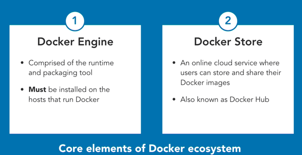
Docker Hub is an excellent source of images to get you started building your own containerized apps.
You can download an image that provides the basic functionality you require
and layer your own application on top of it to create a new custom image.
You can automate the steps for doing this process by writing a Dockerfile.
Dockerfile : is for automating docker image creation
the changes are
copying files into the container from the local filesystem,
and running various tools and utilities to compile code.
When finished, you would use the docker commit command to save the changes to a new image.
# sample dockerfile
#----------------------------------------

# FROM statement downloads the specified image and creates a new container based on this image.
FROM mcr.microsoft.com/dotnet/core/sdk:2.2

# The WORKDIR command sets the current working directory in the container,
# used by the following commands.
WORKDIR /app

# The COPY command copies files from the host computer to the container.
# The first argument (myapp_code) is a file or folder on the host computer.
# The second argument (.) specifies the name of the file or folder to act as
# the destination in the container.
# In this case, the destination is the current working directory (/app).
COPY myapp_code .

# The RUN command executes a command in the container.
# Arguments to the RUN command are command-line commands.
RUN dotnet build -c Release -o /rel

# The EXPOSE command creates configuration in the new image that specifies which ports are intended to be opened when the container is run.
# If the container is running a web app, it's common to EXPOSE port 80.
EXPOSE 80

WORKDIR /rel

# The ENTRYPOINT command specifies the operation the container should run when it starts.
# In this example, it runs the newly built app.
# You specify the command to be run and each of its arguments as a string array.
ENTRYPOINT ["dotnet", "myapp.dll"]
By convention, applications meant to be packaged as Docker images typically have a Dockerfile located in the root of their source code, and it’s almost always named Dockerfile.
docker build -t myapp:v1 .

# The docker build command creates a new image by running a Dockerfile.
# The -f flag indicates the name of the Dockerfile to use.
# The -t flag specifies the name of the image to be created, in this example, myapp:v1.
# The final parameter, ., provides the build context for the source files for the COPY command: the set of files on the host computer needed during the build process.
these commands help to create a customized doker image via command prompt
#------------------------------------------------------
# Customize a Docker image to run your own web app
#------------------------------------------------------

# clone source code
git clone https://github.com/MicrosoftDocs/mslearn-hotel-reservation-system.git

# change the directors
cd mslearn-hotel-reservation-system/src

# create a dockerfile
copy NUL Dockerfile
notepad Dockerfile


# Build and deploy the image using the Dockerfile
docker build -t reservationsystem .

# verify that the image has been created and stored in the local registry
docker image list

# Test the web app
docker run -p 8080:80 -d --name reservations reservationsystem
for running kubernetes cluster the minikube and kubectl must be installed
if you have already installed docker desktop, you don’t need to install the kubectl because docker desktop contains it. Only add the path of the kubectl.exe under your docker folder to the “Path” in your local variables e.g. in my case the path is “C:\Program Files\Docker\Docker\resources\bin”
for installing minikube use
choco install minikube
I do all these steps in Visual Studio Code but you can use any other command prompt environments.
It’s imporant to run the command prompt window as administrator (it’s necessary for running and stopping the cluster).
I installed and started the minikube in CMD Prompt run as admin.
If you have any problem with minikube use delete and start it again.
minikube delete
# Start a Minikube
minikube start   --kubernetes-version=v1.18.3 --addons="dashboard" --addons="metrics-server" --addons="ingress" --addons="ingress-dns" --feature-gates=EphemeralContainers=true

# Get version of the kubectl
Kubectl version

# Get the nodes
kubectl get nodes
# Output is as follows
# NAME       STATUS   ROLES    AGE   VERSION
# minikube   Ready    master   11h   v1.18.3
# Node with role(master) control the cluster.
# Worker nodes are our containers that we deploy.

# Stop Minikube cluster
Minikube stop

# Start the minikube again
Minikube Start
Running Pod/Container
# You have to start minikube before using kubectl

# Create a Pod
kubectl run web --image=nginx
# What we run is a wrapper called Pod

# Get Pods
kubectl get pods

# Get pod information
kubectl describe pod web

# Create Pod in the correct way
kubectl apply -f .\web-declarative.yaml
The web-declarative.yaml file is as follows
apiVersion: v1
kind: Pod
metadata:
  name: web-declarative
  labels:
    site: blog
spec:
  containers:
    - name: web
      image: nginx:1.18.0
Access Pods via Services inside the cluster (loose coupling)
Services make the pod accessible inside the cluster
blue should only know the blue-green service (blue-green is like a DNS).
Service can be created in two ways
with exposing a port of the Pod (kubectl expose pod green –port 8080 .\blue-green.yaml)
wiht applying a service (kubectl apply -f .\blue-green.yaml)
for deploying a service we have to have a yaml file.
The following code to start the pod/green and then deploy service/blue-green
# Deploy a Pod
kubectl apply -f .\green.yaml

# A service is created to make the pod more accessible incide the cluster network
kubectl expose pod green --port 8080 blue-green

# If later want to remove service manually
kubectl delete service blue-green

# This command do the same like kubectl expose
kubectl apply -f .\blue-green.yaml
This is the configuration for service (blue-green.yaml)
Workflow: in service yaml file, we have configured the selector: (refer to a Pod with). It has been refered to a Pod with app: blue-greendsdsd, it means refer to a Pod, which has a app: blue-greendsdsd label.
The blue-green service can talk with all pods that have app: blue-greendsdsd label. This is called loose coupling.
Usually we cannot talk to the Pods (because they are in a cluster, which is a separate machine) and we have provide a way
To talk to a pod via browser we have to create a type of service
This service must open a port and listen to it.
Expose workers to other services within the culster
We create two Pods and one Service
# Deploy all yaml files in the current directory
kubectl apply -f .
# Output is as follows
# service/blue-green created
# pod/blue created
# pod/green unchanged
blue Pod
apiVersion: v1
kind: Pod
metadata:
name: blue
labels:
app: blue-green
spec:
containers:
- name: blue
image: docker.io/mtinside/blue-green:blue
green Pod
apiVersion: v1
kind: Pod
metadata:
  name: green
  labels:
    app: blue-green
spec:
  containers:
    - name: green
      image: docker.io/mtinside/blue-green:green
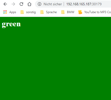
The default type of the service is ClusterIP (type: ClusterIP). To expose a port of service to be accessible from browser the type have to be changed to type: NodePort. The change have to be applied to service with following code.
# Apply changes to a running service
kubectl apply -f .\blue-green.yaml
# output is service/blue-green configured
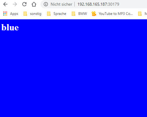
# get IP of the Mnikube
Minikube ip # -> 192.168.165.187
# get the port number of the service
Kubectl get services
# NAME TYPE CLUSTER-IP EXTERNAL-IP PORT(S) AGE
# blue-green NodePort 10.105.57.15 <none> 80:30179/TCP 58m
# check this in your browser
http://192.168.165.187:30179
Sometimes the page is blue and sometimes is green.
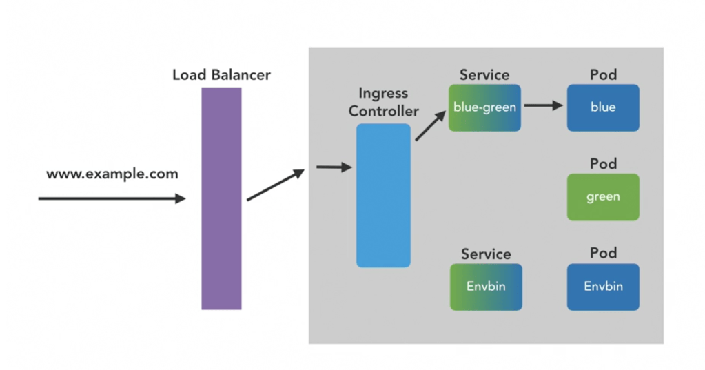
Handling ingress to kubernetes
The workers can be exposed to services within the cluster and to the outside world
But exposing via service with type: NodePort isn’t a sophisticated (service of type load balancer).
In the modern architecture we don’t expose a service to outside.
The Ingress controller is exposed
Ingress controller is for Host- and path-based routing of HTTP traffic
Host- and path-based routing of HTTP traffic as it enters the cluster is handled by which component? Ingress Controller
Which of these is not needed to deploy a container to Kubernetes? an IP address but a name for the wrapper pod object, and a container image to run are necessary.
Where does minikube deploy a Kubernetes cluster? our laptop
Which of these types of service does not allow connections to Pods from outside the cluster? ClusterIP
Discover the services and tools available to automate the deployment and configuration of your Azure infrastructure
Scenario: A clothing manufacturer that’s moving several product design applications to Azure virtual machines. The company needs to scale out to many virtual machines now and in the future. Their current manual process is time consuming and error prone. They want to automate the scale-out process to improve operational abilities. They’re unsure about the tools that are available on Azure to provision compute resources, and where each fits into the overall provisioning process.
Available provisioing solutions are:
Custom scripts (VMs)
Desired State Configuration Extensions (VMs)
Chef Server
Terraform (all resources)
Azure Automation State Configuration
Azure Resource Manager templates (all resources)
Custom Script Extension (VMs)
custom script extension downloads and runs scripts on vms
useful for post deployment configuration, software installation
Note: Take care if your configuration or management task requires a restart. A custom script extension won’t continue after a restart.
How to extend a Resource Manager template
There are several ways
create multiple templates, each defining one piece of the system (then link or nest them together to build a more complete system)
modify an existing template ( that’s often the fastest way to get started writing your own templates)
Example
Create a VM.
Open port 80 through the network firewall.
Install and configure web server software on your VM.
# Requirements:
# Create a VM.
# Open port 80 through the network firewall.
# Install and configure web server software on your VM.

az vm extension set \
  --resource-group $RESOURCEGROUP \
  --vm-name SimpleWinVM \
  --name CustomScriptExtension \
  --publisher Microsoft.Compute \
  --version 1.9 \
  --settings '{"fileUris":["https://raw.githubusercontent.com/MicrosoftDocs/mslearn-welcome-to-azure/master/configure-iis.ps1"]}' \
  --protected-settings '{"commandToExecute": "powershell -ExecutionPolicy Unrestricted -File configure-iis.ps1"}' # the script to enable IIS


# This is the content of the configure-iis.ps1 file
#--------------------------------------------------------------
# Install IIS.
dism /online /enable-feature /featurename:IIS-WebServerRole

# Set the home page.
Set-Content `
  -Path "C:\\inetpub\\wwwroot\\Default.htm" `
  -Value "<html><body><h2>Welcome to Azure! My name is $($env:computername).</h2></body></html>"
#--------------------------------------------------------------
Use Chef’s knife tool to deploy virtual machines and simultaneously apply recipes to them. You install the knife tool on your admin workstation, which is the machine where you create policies and execute commands. Then run your knife commands from your admin workstation.
# The following example shows how a knife command can be used to create a virtual machine on Azure. The command
# simultaneously applies a recipe that installs a web server on the machine.

knife azurerm server create `
    --azure-resource-group-name rg-chefdeployment `
    --azure-storage-account store `
    --azure-vm-name chefvm `
    --azure-vm-size 'Standard_DS2_v2' `
    --azure-service-location 'eastus' `
    --azure-image-reference-offer 'WindowsServer' `
    --azure-image-reference-publisher 'MicrosoftWindowsServer' `
    --azure-image-reference-sku '2016-Datacenter' `
    --azure-image-reference-version 'latest' `
    -x myuser `
    -P yourPassword `
    --tcp-endpoints '80,3389' `
    --chef-daemon-interval 1 `
    -r "recipe[webserver]"
You can also use the Chef extension to apply recipes to the target machines. The following example defines a Chef extension for a virtual machine in an Azure Resource Manager template. It points to a Chef server by using the chef_server_url property. It points to a recipe to run on the virtual machine to put it in the desired state.
A recipe might look like the one that follows. The recipe installs an IIS web server.
#install IIS on the node.
powershell_script 'Install IIS' do
     action :run
     code 'add-windowsfeature Web-Server'
end

service 'w3svc' do
     action [ :enable, :start ]
end
Azure Desired State Configuration (DSC) extensions
Automation State Configuration
Resource Manager templates
Ease of setup
is built into the Azure portal, so setup is eas
are easy to read, update, and store. Configurations define what state you want to achieve. The author doesn’t need to know how that state is reached.
isn’t difficult to set up, but it requires the user to be familiar with the Azure portal.
create Resource Manager templates easily. You have many templates available from the GitHub community, which you can use or build upon. Alternatively, you can create your own templates from the Azure portal.
Management
can get tricky as your infrastructure grows and you accumulate different custom scripts for different resources
democratizes configuration management across servers.
The service manages all of the virtual machines for you automatically. Each virtual machine can send you detailed reports about its state, which you can use to draw insights from this data. Automation State Configuration also helps you to manage your DSC configurations more easily.
is straightforward because you manage JavaScript Object Notation (JSON) files.
Interoperability
can be added into an Azure Resource Manager template. can also deploy it through Azure PowerShell or the Azure CLI.
are used with Azure Automation State Configuration. They can be configured through the Azure portal, Azure PowerShell, or Azure Resource Manager templates.
requires DSC configurations. It works with your Azure virtual machines automatically, and any virtual machines that you have on-premises or on another cloud provider.
You can use other tools to provision Resource Manager templates, such as the Azure CLI, the Azure portal, PowerShell, and Terraform.
Configuration language
write scripts by using many types of commands. e.g. powershell, bash
Use PowerShell
powershell
JSON
Limitations and drawbacks
aren’t suitable for long run scripts or reboots needed scripts
only use PowerShell to define configurations. If you use DSC without Azure Automation State Configuration, you have to take care of your own orchestration and management.
use powershell
JSON has a strict syntax and grammar, and mistakes can easily render a template invalid. The requirement to know all of the resource providers in Azure and their options can be onerous.
Scenario for custom script: The organization you work for has been given a new contract to work for a new client. They have a handful of virtual machines that run on Azure. The development team decides they need to install a small application they’ve written to help increase their team’s productivity and make sure they can meet new deadlines. This application doesn’t require a restart.
Custom script advantages: The custom script extension is good for small configurations after provisioning. It’s also good if you need to add or update some applications on a target machine quickly. It’s imperative for ad-hoc cross-platform scripting.
Scenario for Azure Desired State Configuration State: The organization you work for is testing a new application, which requires new virtual machines to be identical so that the application can be accurately tested. The company wants to ensure that the virtual machines have the exact same configuration settings. You notice that some of these settings require multiple restarts of each virtual machine. Your company wants a singular state configuration for all machines at the point of provisioning. Any error handling to achieve the state should be abstracted as much as possible from the state configuration. Configurations should be easy to read.
Azure Desired State Configuration advantages: DSC is easy to read, update, and store. DSC configurations help you declare the state your machines should be in at the point they are provisioned, rather than having instructions that detail how to put the machines in a certain state. Without Azure Automation State Configuration, you have to manage your own DSC configurations and orchestration. DSC can achieve more when it’s coupled with Azure Automation State Configuration.
Scenario for Azure State Configuration: You learn that the company you work for wants to be able to create hundreds of virtual machines, with identical configurations. They want to report back on these configurations. They want to be able to see which machines accept which configurations without problems. They also want to see those problems when a machine doesn’t achieve a desired state. In addition, they want to be able to feed all of this data into a monitoring tool so they can analyze all of the data and learn from it.
Azure State Configuration advantages: The Azure Automation State Configuration service is good for automating your DSC configurations, along with the management of machines that need those configurations, and getting centralized reporting back from each machine. You can use DSC without Azure Automation State Configuration, particularly if you want to administer a smaller number of machines. For larger and more complicated scenarios that need orchestration, Azure Automation State Configuration is the solution you need. All of the configurations and features that you need can be pushed to all of the machines, and applied equally, with minimal effort.
Scenario for ARM Templates: Each developer should be able to automatically provision an entire group of virtual machines that are identical to what everyone else on the team creates. The developers want to be sure they’re all working in the same environment. The developers are familiar with JSON, but they don’t necessarily know how to administer infrastructure. They need to be able to provision all of the resources they need to run these virtual machines in an easy and rapid manner.
ARM Template advantages: Resource Manager templates can be used for small ad-hoc infrastructures. They’re also ideal for deploying larger infrastructures with multiple services along with their dependencies. Resource templates can fit well into developers’ workflows. You use the same template to deploy your application repeatedly during every stage of the application lifecycle.
third-party solution comparison
Chef
Terraform
Ease of setup
runs on the master machine, and Chef clients run as agents on each of your client machines. You can also use hosted Chef and get started much faster, instead of running your own server.
To get started with Terraform, download the version that corresponds with your operating system and install it.
Management
can be difficult because it uses a Ruby-based domain-specific language. You might need a Ruby developer to manage the configuration.
files are designed to be easy to manage.
Interoperability
only works under Linux and Unix, but the Chef client can run on Windows.
supports Azure, Amazon Web Services, and Google Cloud Platform.
Configuration language
uses a Ruby-based domain-specific language.
uses Hashicorp Configuration Language (HCL). You can also use JSON.
Limitations and drawbacks
The language can take time to learn, especially for developers who aren’t familiar with Ruby.
Because Terraform is managed separately from Azure, you might find that you can’t provision some types of services or resources.
Scenario for Chef Server: Your organization has decided to let the developers create some virtual machines for their own testing purposes. The development team knows various programming languages and recently started writing Ruby applications. They’d like to scale these applications and run them on test environments. They’re familiar with Linux. The developers run only Linux-based machines and destroy them after testing is finished.
Chef Server advantages: Chef is suitable for large-scale infrastructure deployment and configuration. Chef makes it easy for you to automate the deployment of an entire infrastructure, such as in the workflow of a development team.
Scenario for Terraform: Your organization has gained a new client who wants to create multiple virtual machines across several cloud providers. The client has asked you to create three new virtual machines in Azure and one other in the public cloud. The client wants the virtual machines to be similar. They should be created by using a script that works with both providers. This approach will help the client have a better idea of what they’ve provisioned across providers.
Terraform advantages: With Terraform, you can plan the infrastructure as code and see a preview of what the code will create. You can have that code peer reviewed to minimize errors in configuration. Terraform supports infrastructure configurations across different cloud service providers.
Example
# Source : https://docs.microsoft.com/en-us/learn/modules/choose-compute-provisioning/5-exercise-deploy-template
# Clone the configuration and template
git clone https://github.com/MicrosoftDocs/mslearn-choose-compute-provisioning.git

cd mslearn-choose-compute-provisioning
code Webserver.ps1

# file content
Configuration Webserver
{
    param ($MachineName)

    Node $MachineName
    {
        #Install the IIS Role
        WindowsFeature IIS
        {
            Ensure = "Present"
            Name = "Web-Server"
        }

        #Install ASP.NET 4.5
        WindowsFeature ASP
        {
            Ensure = "Present"
            Name = "Web-Asp-Net45"
        }

        WindowsFeature WebServerManagementConsole
        {
            Name = "Web-Mgmt-Console"
            Ensure = "Present"
        }
    }
}

# configure template
code template.json

# replace modulesUrl parameter in template
"modulesUrl": {
    "type": "string",
    "metadata": {
        "description": "URL for the DSC configuration module."
    }
},

# Validate your template
az deployment group validate \
    --resource-group learn-46d7acf0-e3c7-48c8-9416-bf9f3875659c \
    --template-file template.json \
    --parameters vmName=hostVM1 adminUsername=serveradmin

# Deploy your template
az deployment group create \
    --resource-group learn-46d7acf0-e3c7-48c8-9416-bf9f3875659c \
    --template-file template.json \
    --parameters vmName=hostVM1 adminUsername=serveradmin

az resource list \
    --resource-group learn-46d7acf0-e3c7-48c8-9416-bf9f3875659c \
    --output table \
    --query "[*].{Name:name, Type:type}"

echo http://$(az vm show \
    --show-details \
    --resource-group learn-46d7acf0-e3c7-48c8-9416-bf9f3875659c \
    --name hostVM1 \
    --query publicIps \
    --output tsv)
New-AzResourceGroup -Name <resource-group-name> -Location <resource-group-location> #use this command when you need to create a new resource group for your deployment
New-AzResourceGroupDeployment -ResourceGroupName <resource-group-name> -TemplateUri https://raw.githubusercontent.com/Azure/azure-quickstart-templates/master/101-vm-simple-windows/azuredeploy.json
CLI
az group create --name <resource-group-name> --location <resource-group-location> #use this command when you need to create a new resource group for your deployment
az group deployment create --resource-group <my-resource-group> --template-uri https://raw.githubusercontent.com/Azure/azure-quickstart-templates/master/101-vm-simple-windows/azuredeploy.json
Example
# define parameters for ARM template
RESOURCEGROUP=learn-quickstart-vm-rg
LOCATION=eastus
USERNAME=azureuser
PASSWORD=$(openssl rand -base64 32)

# create resource group
az group create --name $RESOURCEGROUP --location $LOCATION

# validate the template
az deployment group validate \
  --resource-group $RESOURCEGROUP \
  --template-uri "https://raw.githubusercontent.com/Azure/azure-quickstart-templates/master/101-vm-simple-windows/azuredeploy.json" \
  --parameters adminUsername=$USERNAME \
  --parameters adminPassword=$PASSWORD \
  --parameters dnsLabelPrefix=$DNS_LABEL_PREFIX

# deploy the template
az deployment group create \
  --name MyDeployment \
  --resource-group $RESOURCEGROUP \
  --template-uri "https://raw.githubusercontent.com/Azure/azure-quickstart-templates/master/101-vm-simple-windows/azuredeploy.json" \
  --parameters adminUsername=$USERNAME \
  --parameters adminPassword=$PASSWORD \
  --parameters dnsLabelPrefix=$DNS_LABEL_PREFIX

  # verify the deployment
  az deployment group show \
  --name MyDeployment \
  --resource-group $RESOURCEGROUP


  # list the vms
  az vm list \
  --resource-group $RESOURCEGROUP \
  --output table
This document presents the Azure Storage’s Best Practices.
Call Storage Rest API
The Storage’s REST API can be called as follows over HTTP/HTTPS. The output of this call is XML therefore the pre-built client libraries can help to work with XML output.
GET https://[url-for-service-account]/?comp=list&include=metadata

# Custom Domain can be used as well
# Https://[StorageName].blob.core.windows.net/
# Https://[StorageName].queue.core.windows.net/
# Https://[StorageName].table.core.windows.net/
# Https://[StorageName].file.core.windows.net/
Access Key & API Endpoint: Each storage has a unique access key.
Shared Access Signature (SAS): It can have grained permission
How to secure the authentication values
Using Key/value
Best Practice 1
Scenario
You’re building a photo-sharing application. Every day, thousands of users take pictures and rely on your application to keep them safe and make them accessible across all their devices. Storing these photos is critical to your business, and you would like to ensure that the system used in your application is fast, reliable, and secure. Ideally, this would be done without you having to build all these aspects into the app. [Source]
# Create an Azure Storage
az storage account create \
        --resource-group learn-242f907f-37b3-454d-a023-dae97958e5d9 \
        --kind StorageV2 \
        --sku Standard_LRS \
        --access-tier Cool \
        --name parisalsnstorage

# Get the ConnectionString of the Storage
az storage account show-connection-string \
    --resource-group learn-242f907f-37b3-454d-a023-dae97958e5d9 \
    --name parisalsnstorage \
    --query parisalsnstorage
2. Create an Application
# Create a DotNet Core Application
# Create the project in spesific folder with -o / --output <folder-name>
dotnet new console --name PhotoSharingApp

# Change to project folder
cd PhotoSharingApp

# Run the project
dotnet run

# Create a appsettings.json file. The Storage connection string is kept here.
# This is the simple version
touch appsettings.json
3. Configure Application
# Add Azure Storage NuGet Package
dotnet add package WindowsAzure.Storage

# Run to test the project
dotnet run

# Edit the appsettings.json
code .
After the appsettings.json file is opned in Editor change the content as follows
{
  "StorageAccountConnectionString": "The Storage Connection String must be placed here"
}
The next file is PhotoSharingApp.csproj. It have to be changed as follows
using System;
using Microsoft.Extensions.Configuration;
using System.IO;
using Microsoft.WindowsAzure.Storage;
using System.Threading.Tasks;

namespace PhotoSharingApp
{
    class Program
    {
        static async Task Main(string[] args)
        {
            var builder = new ConfigurationBuilder()
                .SetBasePath(Directory.GetCurrentDirectory())
                .AddJsonFile("appsettings.json");

            var configuration = builder.Build();
            var connectionString = configuration["StorageAccountConnectionString"];

            # Simplest way to initialize the object model via either .TryParse or .Parse
            if (!CloudStorageAccount.TryParse(connectionString, out CloudStorageAccount storageAccount))
            {
                Console.WriteLine("Unable to parse connection string");
                return;
            }

            var blobClient = storageAccount.CreateCloudBlobClient();
            var blobContainer = blobClient.GetContainerReference("photoblobs");
            bool created = await blobContainer.CreateIfNotExistsAsync();

            Console.WriteLine(created ? "Created the Blob container" : "Blob container already exists.");
        }
    }
}
Best Practice 2
Best Practice n
I’m working on the content..it will be published soon 🙂
Amazon DynamoDB is a fast NoSQL database service for all applications that need consistent, single-millisecond latency at any scale. It is a fully managed database and supports both document and key-value data models. Its flexible data model and reliable performance make it a great fit for mobile, web, gaming, ad-tech, IoT, and many other applications. [Source]
Create DynamoDB
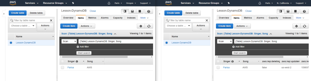
Create Global table
For creating Global table, the DynamoDb Stream must be enabled. The following figure demonstrates how to enable it.
Then we use the Global Tables tab and Add region.
After I added a new item to “Oregon” table, the values would be added to the “California” as well.
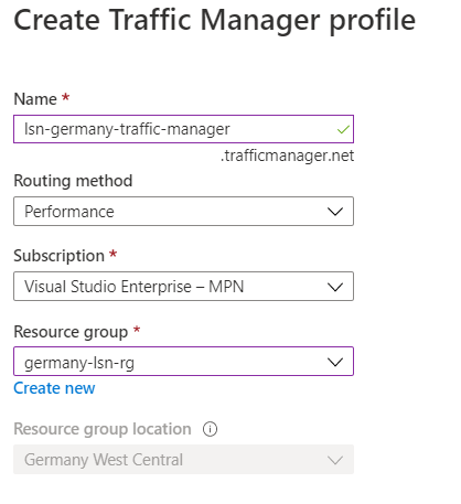
Traffic Manager: provides DNS load balancing to your application, so you improve your ability to distribute your application around the world. Use Traffic Manager to improve the performance and availability of your application.
Application Gateway vs. Traffic Manager: The traffic manager only directs the clients to the IP address of the service that they want to go to and the Traffic Manager cannot see the traffic. But Gateway sees the traffic.
Load balancing the web service with the application gateway
Improve application resilience by distributing the load across multiple servers and using path-based routing to direct web traffic.
Application gateway works based on Layer 7
Scenario: you work for the motor vehicle department of a governmental organization. The department runs several public websites that enable drivers to register their vehicles and renew their driver’s licenses online. The vehicle registration website has been running on a single server and has suffered multiple outages because of server failures.
Link to a sample code – Terraform implementation of Azure Application Gateway – Terraform implementation of Azure Application Gateway’ Backend pool with VM – Terraform implementation of Azure Application Gateway’s HTTPS with Keyvault as Ceritficate Store
Load balancing with Azure Load Balancer
Azure load balancer for resilient applications against failure and for easily scaling
Azure load balancer works in layer 4
LB spreads/distributes requests to multiple VMs and services (user gets service even when a VM is failed) automatically
LB provides high availability
LB uses a Hash-based distribution algorithm (5-tuple)
5-tuple hash map traffic to available services (Source IP, Source Port, Destination IP, Destination Port, Protocol Type)
supports an inbound, and outbound scenario
Low latency, high throughput, scale up to millions of flows for all TCP and UDP applications
Isn’t a physical instance but only an object for configuring infrastructure
For high availability, we can use LB with availability set (protect for hardware failure) and availability zones (for data center failure)
Scenario: You work for a healthcare organization that’s launching a new portal application in which patients can schedule appointments. The application has a patient portal and web application front end and a business-tier database. The database is used by the front end to retrieve and save patient information. The new portal needs to be available around the clock to handle failures. The portal must adjust to fluctuations in load by adding and removing resources to match the load. The organization needs a solution that distributes work to virtual machines across the system as virtual machines are added. The solution should detect failures and reroute jobs to virtual machines as needed. Improved resiliency and scalability help ensure that patients can schedule appointments from any location [Source].
Link to a sample code to deploy simple Nginx web servers with Availability Set and Public Load Balancer.
Load Balancer SKU
Basic Load Balancer
Port forwarding
Automatic reconfiguration
Health Probe
Outbound connections through source network address translation (SNAT)
Diagnostics through Azure log analytics for public-facing load balancers
Can be used only with availability set
Standard Load Balancer
Supports all the basic LB features
Https health probe
Availability zone
Diagnostics through Azure monitor, for multidimensional metrics
High availability (HA) ports
outbound rules
guaranteed SLA (99,99% for two or more VMs)
Load Balancer Types
Internal LB
distributes the load from internal Azure resources to other Azure resources
no traffic from the internet is allowed
External/Public LB
Distributes client traffic across multiple VMS.
Permits traffic from the internet (browser, module app, other resources)
public LB maps the public IP and port of incoming traffic to the private IP address and port number of the VM in the back-end pool.
Distribute traffic by applying the load-balancing rule
Distribution modes
Lb distributes traffic equally among vms
distribution modes are for creating different behavior
When you create the load balancer endpoint, you must specify the distribution mode in the load balancer rule
Prerequisites for load balancer rule
must have at least one backend
must have at least one health probe
Five tuple hash
default of LB
As the source port is included in the hash and can be changed for each session, the client might be directed to a different VM for each session.
source IP affinity / Session Affinity / Client IP affinity
this distribution is known as session affinity/client IP affinity
to map traffic to the server, the 2-tuple hash is used (Source IP, Destination IP) or the 3-tuple (Source IP, Destination IP, Protocol)
Hash ensures that requests from specific clients are always sent to the same VM.
Scenario: Remote Desktop Protocol is incompatible with 5-tuple hash
Scenario: for uploading media files this distribution must be used because for uploading a file the same TCP session is used to monitor the progress and a separate UDP session uploads the file.
Scenario: The requirement of the presentation tier is to use in-memory sessions to store the logged user’s profile as the user interacts with the portal. In this scenario, the load balancer must provide source IP affinity to maintain a user’s session. The profile is stored only on the virtual machine that the client first connects to because that IP address is directed to the same server.
Enhance service availability and data locality with Traffic Manager
Scenario: a company that provides a global music streaming web application. You want your customers, wherever they are in the world, to experience near-zero downtime. The application needs to be responsive. You know that poor performance might drive your customers to your competitors. You’d also like to have customized experiences for customers who are in specific regions for user interface, legal, and operational reasons. Your customers require 24×7 availability of your company’s streaming music application. Cloud services in one region might become unavailable because of technical issues, such as planned maintenance or scheduled security updates. In these scenarios, your company wants to have a failover endpoint so your customers can continue to access its services.
traffic manager is a DNS-based traffic load balancer
Traffic Manager distributes traffic to different regions for high availability, resilience, and responsiveness
it resolves the DNS name of the service as an IP address (directs to the service endpoint based on the rules of the traffic routing method)
it’s a proxy or gateway
it doesn’t see the traffic that a client sends to a server
it only gives the client the IP address of where they need to go
it’s created only Global.
The location cannot be specified because it’s Global
Traffic Manager Profile’s routing methods
each profile has only one routing method
Weighted routing
distribute traffic across a set of endpoints, either evently or based on different weights
weights between 1 to 1000
for each DNS query received, the traffic manager randomly chooses an available endpoint
probability of choosing an endpoint is based on the weights assigned to endpoints
with endpoints in different geographic locations, the best performance endpoint for the user is sent
it uses an internet latency table, which actively track network latencies to the endpoints
Geographic routing
based on where the DNS query originated, the specific endpoint of the region is sent to the user
it’s good for geo-fence content e.g. it’s good for countries with specific terms and conditions for regional compliance
Multivalue routing
to obtain multiple healthy endpoints in a single DNS query
caller can make client-side retries if endpoint is unresponsive
it can increase availability of service and reduce latency associated with a new DNS query
Subnet routing
maps a set of user ip addresses to specific endpoints e.g. can be used for testing an app before release (internal test), or to block users from specific ISPs.
Priority routing
traffic manager profile contains a prioritized list of services
Traffic Manager Profile’s endpoints
endpoint is the destination location that is returned to the client
Types are
Azure endpoints: for services hosted in azure
Azure App Service
public ip resources that are associated with load balancers, or vms
External endpoints
for ip v4/v6
FQDNs
services hosted outside azure either on-prem or other cloud
Nested endpoints: are used to combine Traffic Manager profiles to create more flexible traffic-routing schemes to support the needs of larger, more complex deployments.
Endpoints Types/Targets
Each traffic manager profile can have serveral endpoints with different types
To have a resilience platform all parts must be configured to befault tolerant. But first the level of redundancy and resilienc must be determined.
Fault Tolerant Server-based Services
Server bases services are those that are “instance” based. Services like RDS and ElastiCache are instanced based in that you can run one instance, but you will not have any fault tolerance. In order to gain high availability, you need to tell the service to provision a second instance for the primary instance to failover to, should there be an issue with it.
This model is similar to traditional data center environments. A good way to tell if a service is a server/instance based service or if the service is a pre-existing product that AWS has created a service with (MongoDB, Redis, MySQL, Postgres).
Most of the server based services have similar concepts for handling a hardware failover automatically. This functionality is the same that handles a single availability zone failure. By creating active/standby pairs of servers that replicate and by having each member of the pair in a different availability zone, you create the infrastructure that handles both of these failure modes.
ElastiCache
ElastiCache is one of these services. You will create an ElastiCache cluster that does not have a single point of failure, and that can handle an AZ outage.
First, create an ElastiCache subnet group in the default VPC using each available subnet and
then create a multi-AZ redis cluster.
Elasticache’s Subnet Groups
AWS > Elasticache page > Subnet Groups
The Subnet Groups option is availble on the service page
Then create a new Subnet Groups. Based on the region of the selected VPC the Availability Zone is listed.
We can have only one subnet in each availability zone. See the figure above, I tried to add more but it’s not possible.
As next we create the Redis Cluster. The created Subnet in the previous step, is selected in Subnet Groups.
DynamoDB
DynamoDB is a native AWS service for non-relational databases
It is Multi-AZ by default and can be made Multi-Region with DynamoDB Streams and by creating a Global DynamoDB table
Global table is multi-region and active/active (it means any changes to one table is propagated to sll other tables)
DynamoDB scales to extremely high loads with very fast response times
It also supports configuring a caching layer in front of the database.
DynamoDB Streams allow every change made to a DynamoDB table to be “streamed” into other services. These other services can then choose what actions to take on the different items or operations within the stream.
In DynamoDb each database cintains just one table
This table has just one primary key and optional sort keyby default
It’s possible to have multi primary key, sort key on the table.
Indeces as well
charge is based on operation in seconds
or pay on demand
Automatic scale up and down
DynamoDB Streams And Global Tables
DynamoDB Streams capture all changes made to a DynamoDB Table. This includes only actions that modify the table, not actions that only read from the table.
DynamoDB Global Tables take advantage of DynamoDB Streams the create Multi-Region active/active DynamoDB Tables. This allows you to modify a table in multiple regions and have those changes reflected in all regions.
Multi-Region, active/active data stores are a big deal and extremely useful for use cases that require it.
DynamoDB is a non-relational database. It is a fully managed service created by AWS. With DynamoDB you create tables, but unlike a relational database, each table is completely independent.
DynamoDB is not like the server-based services that AWS offers (RDS, ElastiCache, etc.), it is “serverless” in the sense that you do not have any control over the physical infrastructure that it runs on. You do not pay for the service when you are not using it (except used storage space). Because DynamoDB is different than server-based offerings, the mechanisms for redundancy are also different. DynamoDB offers multi-region, active/active service if you elect it. This is called DyanmoDB Global Tables.
Amazon DynamoDB is a fast NoSQL database service for all applications that need consistent, single-millisecond latency at any scale. It is a fully managed database and supports both document and key-value data models. Its flexible data model and reliable performance make it a great fit for mobile, web, gaming, ad-tech, IoT, and many other applications. [Source]
Fault Tolerant Operations
1- Subnet Groups
To get Multi-AZ availability, you need to configure a Subnet Group (contains subnets in different AZs) within the service. A subnet is attached to an AZ, and creating a grouping of subnets within the service and tells the service where it can place the primary and standby instances of a service.
Based on the service and data volumne, creating a new instance in secondary subnet, can takes diffrent duration.
2- Multiple instances
To reduce downtime to seconds, multi instances have to be created.
3- Multi-AZ checkbox
4- Multi Region Redundancy
Subnet Groups are key to creating Multi-AZ redundancy in server-based services. Subnet Groups define the different availability zones that your service will run in, and having multiple instances allow for fast failover if a single AZ were to go down.
Multi-Region redundancy is more tricky. Depending on the service, it is harder, or not possible to run a service with failover between regions.
Some services allow to have read replica in a second region, but later you have to activate it as primary e.g. Amazon RDS.
Some services don’t have multi region support e.g. Elastic Search.